Edward
The graph below shows the results of the in-class experiment.
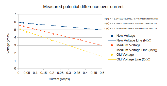
Each equation can be written in the form $V=-R_{I}I + \epsilon$.
Interpreting the y-intercept of each line as the $EMF$ for each respective battery, and the gradient of each line to be the inverse internal resistance for each respective battery
Hence, the data indicates that as a battery depletes, it's $EMF$ decreases, and it's $R_{I}\text{ (Internal Resistance)}$ increases.
If a battery had 0 internal resistance($R_{I}$), then electrons would be able to freely transfer between the negative and positive terminals of the battery. As the $EMF$ is fixed, the current that passes through would approach infinity assuming negligible resistance from the rest of the circuit(i.e. just connecting the terminals with an external wire). This is suggested via Ohm's law, $V=IR$. Re-arranging for $I$ gives $I=\frac{V}{R}$. Hence, as $R_{I}\to{0}$, $I\to \infty$. So electrons would move through the circuit at a very fast speed, resulting in a short circuit. This would amplify the negative effects (rapid heating, wasted energy) of short circuiting, as the circuit's current would be much higher with no $R_{I}$ to oppose it.
If we measure the voltage of the battery when current is 0, then according to $V=IR$, as $I\to{0}$, $V\to{0}$. So, the potential difference across the battery should be 0. Furthermore, as some voltage is lost due to the internal resistance of the battery, not all of the $EMF$ is transformed into voltage for the circuit. Hence, the measured voltage will be lower than the $EMF$.
As voltmeters do not have infinite resistance, so according to $V=IR$, if $R\neq \infty$, then $I\neq{0}$. Hence, the voltmeter will draw some current, hence as $V=IR$, the voltmeter will thus consume voltage, changing the voltage of the circuit/circuit component being measured.
The graph yields the following table, with additional data not present on the graph.
| New Battery | Medium Battery | Old Battery | |
|---|---|---|---|
| $EMF\ (\text{V})$ | 5.93385 | 5.59318 | 5.08707 |
| $R_{I} \ (\Omega)$ | 1.94419 | 5.20801 | 7.08264 |
| Measured V of battery (w/o circuit) $(\text{V})$ | 6.00000 | 5.68000 | 5.58000 |
From the table, $EMF$ appears to be lower than the directly measured voltage, which suggests a systematic error in the experiment causing the $EMF$ calculated to be too low.
The table suggests that as the battery goes flatter the $EMF$ decreases. This is explained through the process of which batteries provide voltage, through a chemical process by which electrons are transferred from an anode and supplied to a cathode. This results in the consumption of finite electron donors (reductants) to finite electron acceptors (oxidants). Hence, as the battery operates, the amount of these finite components to the battery deplete, resulting in a reduced $EMF$ overtime.
From the table, the $R_{I}$ increased as the battery became flatter. This is further explained through the battery discharge process, as the operation of the battery causes numerous factors to change with increase the internal resistance. For example, as a battery operates it may consume ions from an electrolyte, resulting in the concentration of the specific ion decreasing. This increases $R_{I}$ as the electrolyte now has a lower ion concentration, and hence is less effective in completing the internal electrical circuit necessary for the battery to discharge.
The difference between alkaline and heavy-duty batteries was not tested during the experiment, however based on the specific chemical processes and operating environment of both types of batteries, the alkaline battery has the lower $R_{I}$. This is because the internals of the alkaline battery tend to be at a higher temperature, resulting in the electrolyte being able to move faster, hence there is a reduced internal resistance.
As batteries are used, the table indicates that $R_{I}$ increases. Hence, as $EMF$ is constant, according to $V=IR$, the current of the circuit is decreased. Hence, components, such as a light globe for a torch, will have a lower $I$ but a constant $R$, hence as $V=IR$ the voltage drop for the component will be lower, hence old torches will have dimmer lights.
A power pack is an electrical device that stores electricity. However, as electricity (in the form of electrons) cannot remain stationary, they must be transferred through some form of circuit. As the electrons pass through the circuit, they must encounter resistance from the material of the circuit, i.e. the metal of the wire. Hence, power packs must have internal resistance.